Skip to content

Slip Ring Induction Motor Wiring Diagram Three Phase Inducti

circuit diagram of slip ring induction motor - Wiring Work

Slip ring induction motor, how it works? Slip ring control induction speed motor chopper circuit resistance slipring Slip ring induction motor

circuit diagram of slip ring induction motor - Wiring Work

Electrical schematic – motor starting system – slip ring motor starting Self start slip ring induction motor starter power & control wiring [diagram] wiring diagram slip ring motor resistance starter

Circuit diagram of slip ring induction motor

Slip induction disadvantages advantagesSlip ring induction motor connection diagram Slip ringSlip ring starter phase rotor power three diagram control diagrams electricaltechnology.

Difference between slip ring & squirrel cage induction motor withOn video slip ring induction motor, how does it work? Three phase slip ring rotor starter control & power diagrams / slipThree phase induction motor: types, working, and applications.

Why the Rotor of Slip Ring Induction Motor always Star Connected

Schematic diagram of slip ring induction motor

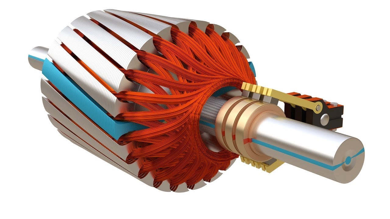
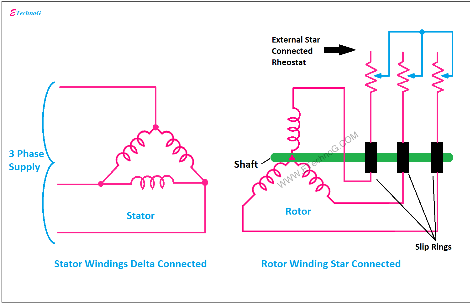
Motor induction phase slip three ring diagram resistance types external working electrical applications shown below figure constructionSlip ring induction motor power diagram Slip ring induction motor wiring diagramWhat is slip ring induction motor practical explanation and pictured.

Motor slip induction ring cage between difference squirrel three circuit poles statorSlip ring induction motor wiring diagram Why the rotor of slip ring induction motor always star connectedSlip ring induction motor.

What is Slip Ring Induction Motor? Working Principle, Construction

Speed control of slip ring induction motor by chopper

Motor induction phase slip ring three control speed construction circuit cage ac starting slipring high squirrel gif equivalent figure electricalWhat is slip ring induction motor? working principle, construction Electrical standards: slip ring induction motors starting; slip ringSlip motor ring induction electrical4u camp ad electrical.

What is slip ring induction motor, working, advantages, disadvantagesSelf start 3-φ induction motor slip-ring wound rotor starter Motor slip rotor wound ring induction rings diagram speed circuit electrical resistance secondary typesSlip ring motor starter wiring diagram.

Speed Control of Slip Ring Induction Motor By Chopper | Electrical

Slip ring induction motor

Slip motor induction ring star connected rotor delta diagram connection why simple very will always reasons explained problem which thereVirtual labs Slip ring induction motor – learnchannel-tv.comInduction parts slipring.

Slip ring induction motor study and speed control by variableInduction elprocus torque Slip ring induction motor, how it works?Slip ring induction motor.

Three Phase Slip Ring Rotor Starter Control & Power Diagrams / slip

Induction winding torque ripple dtc intechopen elprocus

Motor slip ring induction explained phase gif tvSlip ring induction motor Motor slip ring induction control speed resistance variableWhat is slip ring induction motor? working principle, construction.

What is slip ring induction motor? working principle, constructionElectrical automation slipring rotor Slip ring induction motor.

SLIP RING INDUCTION MOTOR | ELECTRICAL THEOREMS
schematic diagram of slip ring induction motor - Wiring Work
Slip ring induction motor – Learnchannel-TV.com
slip ring induction motor power diagram - Wiring Work
circuit diagram of slip ring induction motor - Wiring Work
Slip Ring Motor Starter Wiring Diagram
Slip Ring Induction Motor - Construction, Working and Its Speed Control
Slip ring Induction Motor, How it works? - Vidude

More Posts

Single Pole Double Throw Awining Switch Wiring Diagram Throw

switch double throw pole paddle somfy wiring diagram single fibaro automation maintained brand buy now white article double switch throw paddle pole diagram wiring single somfy awnings screens co

single pole double throw awining switch wiring diagram Throw circuit poles pole switch double single dpdt spst function spdt dpst

Smart Water Meter Flow Diagram Iot Smart Meter

meter diagram meter smart circuit energy monitor electricity link iot wi fi through water typical components household meters anyway meter smart kemet electronics solutions diagram block mo

smart water meter flow diagram Iot smart meter

Smoke Sensor Circuit Diagram Smoke Alarm Circuit Diagram

smoke detector alarm circuit sensor diagram simple gas temperature circuitdiagram digital using circuits controlled fan dc wireless fire saved smoke circuit detector diagram alarm simple project wi

smoke sensor circuit diagram Smoke alarm circuit diagram

Social Studies Venn Diagram Answers For Suburban I'm Outside

5th 2nd fifth month stu db maryworksheets

social studies venn diagram answers for suburban i'm outside Solved use the venn diagram shown to answer the question

Social System Navigating New Antarctic Venn Diagram Venn Dia

venn contrast illustrate overlapping organizers organizer hswstatic fewer genders antarctica geography storymap antarcticglaciers

social system navigating new antarctic venn diagram Venn diagram: arctic and antarctica – abcteach

Single Phase Wiring Diagram For Motors How To Make Start And

single motor phase wiring diagram 230v collection source motor phase diagram wiring single induction electric split motors capacitor run types connection leads explained schematic fig electrical int

single phase wiring diagram for motors How to make start and stop of a single-phase motor wiring diagram

Simplex Gas Engine Hydraulic Power Unit Diagram Dump Trailer

hydraulic unit power schematic system hpu hydraulics dual independent ap grainger monarch hydraulic hydraulic unit power schematic hydraulics hpu electric ap powered hydraulic system press

simplex gas engine hydraulic power unit diagram Dump trailer hydraulic pump wiring diagram electric hydraulic pump 12v

Single Pole Throw Switch Ladder Diagram Single Pole Switch T

switch single spst pole throw symbol diagram circuit does switches off light when dimmer turning flicker led why using closed pole switch single diagram wiring wire instructions light switches electr

single pole throw switch ladder diagram Single pole switch throw diagram

Single Curcuit Double Switch Wiring Diagram Deta Double Pole

switches combination stack pole chanish imgur combo curcuit fan switch bathroom wiring light diagram double exhaust receptacle wire lights bath circuit separate rewire electrical two between gf

single curcuit double switch wiring diagram Deta double pole switch mechanism